- 您现在的位置:买卖IC网 > Sheet目录323 > DV164131 (Microchip Technology)KIT STARTER PICKIT 3
Hardware Specification
10.6
STANDARD COMMUNICATION HARDWARE
For standard debugger communication with a target ( Section 2.3 “Debugger to
Target Communication” , “Standard ICSP Device Communication“), use an adapter
with an RJ-11 connector.
To use this type of communication with a header board, you may need a device-specific
Processor Pak, which includes an 8-pin connector header board containing the desired
ICE/ICD device and a standard adapter board.
Note:
Older header boards used a 6-pin (RJ-11) connector instead of an 8-pin
connector, so these headers may be connected directly to the debugger.
For more on available header boards, see the “ Header Board Specification”
(DS51292).
10.6.1
Standard Communication
The standard communication is the main interface to the target processor. It contains
the connections to the high voltage (V PP ), V DD sense lines, and clock and data
connections required for programming and connecting with the target devices.
The V PP high-voltage lines can produce a variable voltage that can swing from 1.8 to
14 volts to satisfy the voltage requirements for the specific emulation processor.
The V DD sense connection draws current from the target processor.
The clock and data connections are interfaces with the following characteristics:
? Clock and data signals are in high-impedance mode (even when no power is
applied to the PICkit 3 programmer/debugger system)
? Clock and data signals are protected from high voltages caused by faulty targets
systems, or improper connections
? Clock and data signals are protected from high current caused from electrical
shorts in prototype or target systems
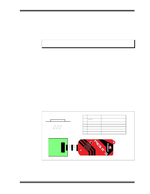
FIGURE 10-1:
6-PIN STANDARD PINOUT
Standard Socket
Pin
1
Name
MCLR/V PP
Power
Function
1
2
4 6
3 5
Bottom of
Target Board
2
3
4
5
V DD _TGT
GND
PGD (ICSPDAT)
PGC (ICSPCLK)
Power on target
Ground
Standard Com Data
Standard Com Clock
? 2009 Microchip Technology Inc.
6
LVP
Low Voltage Programming
DS51795A-page 61
发布紧急采购,3分钟左右您将得到回复。
相关PDF资料
DV164132
KIT EVAL F1 FOR PIC12F1/PIC16F1
DV243003
KIT STARTER FOR SRL MEM PRODUCTS
DVA1001
ADAPTER FOR PIC16F716 18DIP
DVA1004
DEVICE ADAPTER 8/14/20DIP
E3R-D12GP-P
RELAY RCVR PLUG-IN DIMMER
E3R-R12-3HOTP
RCVR 3WIRE RELAY 120V
E3R-R12GP
RCVR PLUG-IN RELAY
E3T-MICFP-40
CONVERTER 4-CH SLT SENSOR
相关代理商/技术参数
DV164131
制造商:Microchip Technology Inc 功能描述:PICKIT 3 DEBUG EXPRESS
DV164131-XLP
制造商:Microchip Technology Inc 功能描述:KIT DEV PICKIT 3-XLP/NANOWAT
DV164132
功能描述:开发板和工具包 - PIC / DSPIC F1 Evaluation Kit RoHS:否 制造商:Microchip Technology 产品:Starter Kits 工具用于评估:chipKIT 核心:Uno32 接口类型: 工作电源电压:
DV164132
制造商:Microchip Technology Inc 功能描述:PIC12F1xxx/PIC16F1xxx F1 Evaluation Kit
DV164133
功能描述:电源管理IC开发工具 Energy Harvesting Development Tool
RoHS:否 制造商:Maxim Integrated 产品:Evaluation Kits 类型:Battery Management 工具用于评估:MAX17710GB 输入电压: 输出电压:1.8 V
DV164136
功能描述:开发板和工具包 - PIC / DSPIC PIC18F DEV Kit (with PICkit 3) RoHS:否 制造商:Microchip Technology 产品:Starter Kits 工具用于评估:chipKIT 核心:Uno32 接口类型: 工作电源电压:
DV164139
功能描述:开发板和工具包 - PIC / DSPIC Lo PIn Count USB Dev Kit (w/PICkit 3) RoHS:否 制造商:Microchip Technology 产品:Starter Kits 工具用于评估:chipKIT 核心:Uno32 接口类型: 工作电源电压:
DV17K3225T
制造商:SEI Stackpole Electronics Inc 功能描述:- Tape and Reel 制造商:SEI Stackpole Electronics Inc 功能描述:Var MOV 17VAC/22VDC 100A 27V 3225 SMD T/R
